A horn antenna should be selected from frequency-dependent data and the complete RF chain, not from one peak gain number. Buyers should define the required frequency segments, coverage angle, polarization, power at the antenna input, connector, feeder loss, mounting environment and acceptance method before comparing quotations.
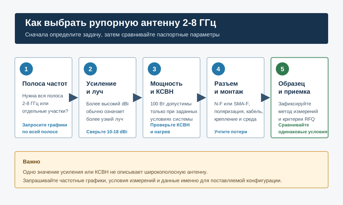
Quick answer: for a 2GHz-8GHz wideband horn, request gain and VSWR plots across the full band, horizontal and vertical beamwidth data, polarization, connector configuration, continuous and peak power conditions, mechanical drawings and a sample acceptance report. A quoted range such as 10-18dBi is useful only when the corresponding frequencies and test conditions are shown.
What a 2GHz-8GHz Horn Antenna Is Used For
A horn antenna transforms energy from a waveguide or feed structure into a directional free-space beam. Compared with many compact panel or omnidirectional antennas, a horn can offer predictable directionality, relatively stable broadband behavior and a mechanical form that is straightforward to aim.
Professional uses can include authorized RF testing, EMC work, laboratory measurements, direction-finding support, communications research, system integration and lawful counter-UAS projects. The antenna does not determine whether a transmission is permitted. Frequency use, radiated power and operating authority must be confirmed for the destination and application.
1. Define the Required Frequency Coverage
“2GHz-8GHz” describes a wide span, but it does not guarantee identical gain, match or beamwidth at every point. Start the RFQ with the actual operating segments and explain whether the system must sweep, monitor, test or transmit continuously across them.
- Full-band requirement: ask for plots from 2GHz to 8GHz with a readable frequency scale.
- Selected sub-bands: state the exact center frequencies and occupied bandwidths that matter to the project.
- Measurement use: ask about calibration data, uncertainty and repeatable positioning.
- System integration: provide the output interface, cable length and expected power at each band.
Do not accept a single “working frequency” line as proof of broadband performance. Ask which parameter sets the usable-band limit: VSWR, gain, radiation pattern, connector, power or another constraint.
2. Compare Gain Together with Beamwidth
Gain describes how strongly an antenna concentrates radiation in a direction relative to a reference. Higher gain usually comes with a narrower beam, so it is not automatically better. A narrow beam can improve directional concentration but requires more accurate pointing and may leave gaps when the protected or measured area is wide.
For the JianHong reference model, the stated gain range is 10-18dBi across 2GHz-8GHz. Procurement should still request the gain value by frequency and the horizontal and vertical half-power beamwidth. These values let the integrator judge whether one antenna, mechanical scanning or multiple sectors are required.
| Buyer question | Why it matters | Evidence to request |
|---|---|---|
| What is the gain at each project band? | Peak gain may occur only at one end of the range | Gain-versus-frequency plot or tabulated measured values |
| What are the horizontal and vertical beamwidths? | Coverage and pointing tolerance depend on both planes | Radiation patterns at representative frequencies |
| How large are the sidelobes? | Unwanted sensitivity or radiation outside the main beam can affect the system | Normalized polar plots and the measurement setup |
| Is the polarization fixed? | Polarization mismatch creates additional loss | Polarization definition and mounting orientation |
3. Read VSWR as a Frequency-Dependent Result
VSWR indicates how well the antenna input is matched to the transmission line. A lower value generally means less power is reflected back toward the source, but the complete result depends on frequency, cable, adapters and installation.
The reference antenna specifies typical VSWR of 1.5 and a maximum of 2.0. The buyer should clarify whether the maximum applies across the entire 2GHz-8GHz range, how it was measured, which connector was installed and whether the quoted result is for a production sample or a design target.
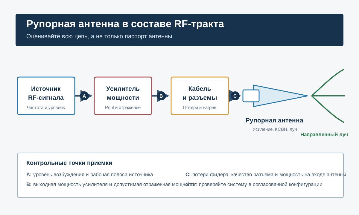
For high-power integration, define an allowable reflected-power or return-loss limit for the complete connected system. The amplifier protection behavior should also be reviewed; antenna matching alone cannot guarantee that the power amplifier remains within its safe operating conditions.
4. Verify Power Handling Under Real Conditions
A “100W” power rating is incomplete without conditions. Buyers should ask whether the number is continuous-wave, average, pulsed or peak power; at which frequency it applies; which connector is fitted; and what ambient temperature, duty cycle and airflow were used.
- State maximum power at the antenna input after feeder losses.
- Define waveform, duty cycle and transmission duration.
- Confirm connector and cable ratings at the highest project frequency.
- Specify ambient temperature, enclosure and nearby heat sources.
- Require inspection for connector heating, arcing, deformation and match drift.
Do not calculate radiated performance from amplifier nameplate power alone. Cable and adapter losses reduce delivered power, while gain changes with frequency. Any EIRP calculation should use agreed values for the operating band and installation.
5. Choose N-F or SMA-F from the Complete Interface
The reference product is available with N-F and optional SMA-F interfaces. The connector choice should follow frequency, delivered power, cable type, mechanical durability, available adapters and service practice rather than convenience alone.
N-type connectors are common in field RF systems and can provide a robust interface. SMA interfaces are compact and widely used in laboratory equipment, but the exact connector grade and power capability matter. Avoid unnecessary adapter chains because every interface adds loss, mismatch and a possible maintenance point.
6. Include Cable Loss and Connector Quality
Feeder loss normally rises with frequency. A cable run that is acceptable at 2GHz may create materially more loss at 8GHz. Ask the supplier or integrator to provide cable type, length, insertion loss by frequency, connector installation method and bend-radius requirements.
For repeatable measurements, label cable assemblies and record their measured loss. For outdoor or mobile use, add sealing, strain relief, grounding, vibration and inspection requirements. A high-quality antenna connected through an unsuitable feeder will not deliver the expected system performance.
7. Confirm Polarization, Pointing and Mounting
The listed antenna uses linear polarization. The mounting drawing should make the polarization orientation unambiguous. A 90-degree polarization mismatch can cause severe loss, while even a smaller orientation error can change a measurement or coverage result.
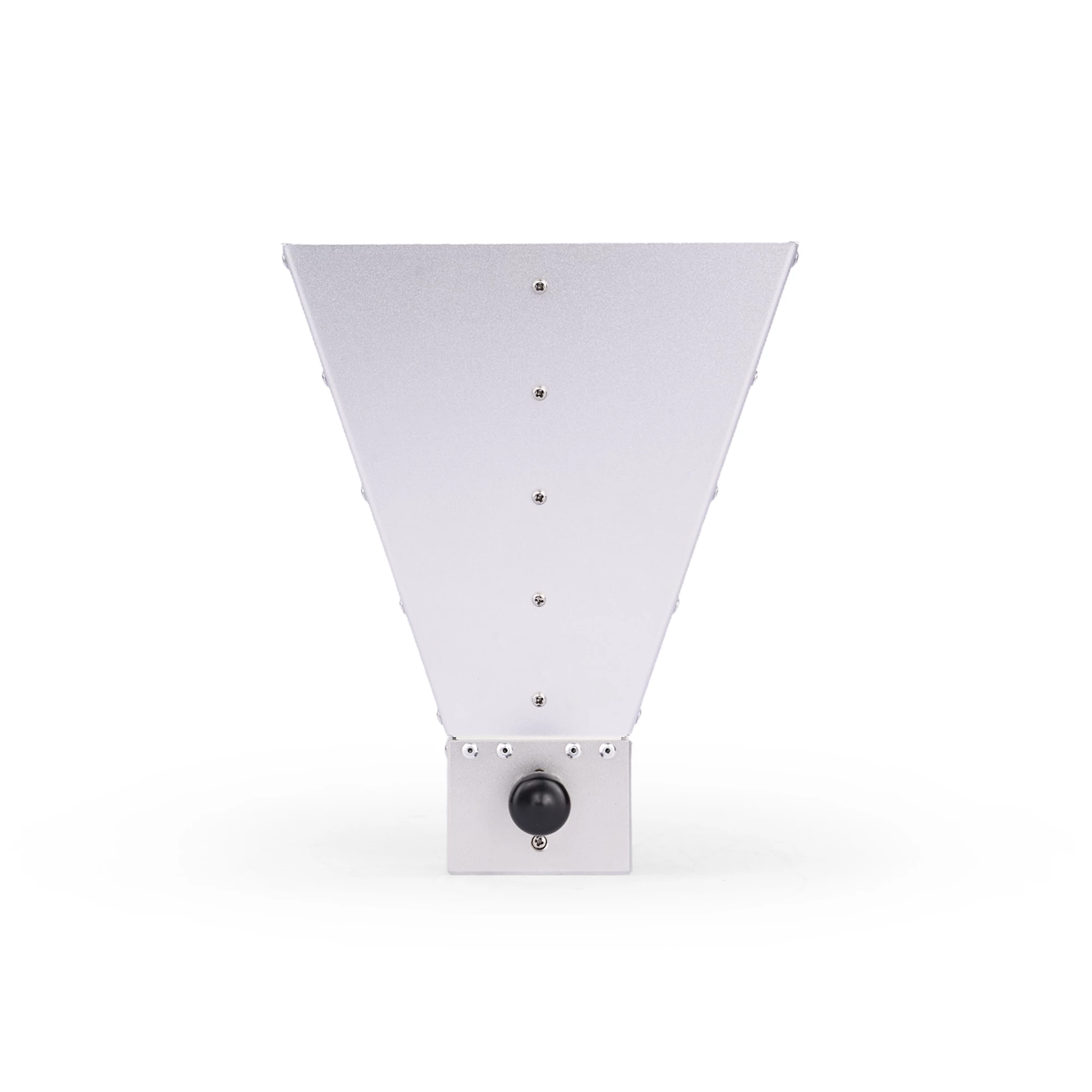
Specify bracket interfaces, allowable pointing error, wind and vibration exposure, indoor or outdoor use, drainage and corrosion protection. The listed dimensions of 285 x 186 x 123mm and mass of about 710g help with an initial mechanical check, but the final drawing and connector clearance should control integration.
8. Reference Specification for Initial Comparison
| Parameter | Reference value | What to confirm in the order |
|---|---|---|
| Frequency range | 2GHz-8GHz | Required sub-bands and full-band plots |
| Gain | 10-18dBi | Value and beamwidth at each project frequency |
| Polarization | Linear | Orientation and mounting reference |
| VSWR | Typical 1.5, maximum 2.0 | Applicable frequencies, sample and measurement setup |
| Maximum input power | Up to 100W | CW/average/peak definition, duty cycle and temperature |
| Connector | N-F; optional SMA-F | Exact interface, cable, adapters and power margin |
| Size and mass | 285 x 186 x 123mm; about 710g | Final drawing, bracket, clearance and tolerance |
View the 2GHz-8GHz high-gain horn antenna product page or compare other antennas and RF accessories. The table is a sourcing reference, not a substitute for the approved technical specification.
9. Horn Antenna RFQ Checklist
Send with the RFQ: application and destination; required frequency bands; receive, test or authorized transmit use; gain and beamwidth targets; polarization; maximum antenna-input power and duty cycle; VSWR or return-loss limit; connector; cable; mounting; environment; quantity; documentation; sample test and acceptance criteria.
Ask the supplier to mark each requirement as complies, deviation or not applicable. Request the datasheet revision, mechanical drawing, measured plots, sample identification and test-equipment information. This creates a reviewable baseline before production.
10. Sample and Batch Acceptance
A practical sample check can include visual inspection, dimensions, connector verification, continuity where applicable, VSWR or return loss across the agreed band, and comparison with a reference gain or pattern method. Production acceptance can use agreed sampling and traceability rather than repeating a full calibration on every unit.
Record cable and adapter corrections, calibration status, distance, alignment, polarization and environmental conditions. Measurements made under different setups should not be compared as though they were directly equivalent.
Common Buying Mistakes
- Selecting the antenna only from the highest dBi number
- Assuming gain, beamwidth and VSWR are constant from 2GHz to 8GHz
- Sending amplifier output power without feeder loss or duty cycle
- Choosing a connector before confirming cable and power requirements
- Ignoring polarization and pointing tolerance
- Accepting a generic plot without sample, setup or frequency scale
- Ordering a batch before approving a representative sample
Frequently Asked Questions
Is an 18dBi horn always better than a 10dBi horn?
No. Higher gain normally produces a narrower beam and tighter pointing requirements. The correct choice depends on coverage angle, distance, frequency and installation.
Can one horn antenna cover the complete 2GHz-8GHz range?
A broadband horn can operate across that range, but gain, beamwidth and VSWR will vary. Review plots across the entire required band.
Is VSWR 2.0 acceptable?
It can be acceptable for some systems, but the limit must be checked against amplifier protection, feeder loss, delivered power and measurement uncertainty.
What does a 100W rating mean?
It is meaningful only with waveform, duty cycle, frequency, connector, temperature and test conditions. Ask the supplier to define each item.
Should I select N-F or SMA-F?
Select the connector with the complete cable and equipment interface in mind. Consider frequency, power, durability, adapter count and service requirements.
What should be approved before a production order?
Approve the specification, plots, drawing, connector, mounting, sample test, labeling, documentation and acceptance method.
Conclusion
The best horn antenna quotation is not the one with the largest isolated number. It is the one that documents performance across the required frequencies and fits the amplifier, feeder, mounting and acceptance plan. Start with the project bands and complete RF chain, then verify the delivered sample.
For a quotation, send your frequency plan, gain and beamwidth targets, antenna-input power, connector, cable, mounting and quantity through the project inquiry form.
Reference framework: IEEE Std 145 antenna terminology, NIST antenna calibration services, ITU Radio Regulations overview and FCC equipment authorization information. Applicable rules and test methods must be verified for the product, destination and use.